Hvac system 2 way dn22 female motorized control valve Idle air control valve wire diagram needed? Valves principle engineeringlearn
Idle Control Valve Diagram
Durango idle valve control dodge air location where 1998 dying please low Valve control air open type installation maintenance controls credits inc source instrumentationtools disassembly reassembly Valve air manual control way position aro grainger zoom tap
8+ pto air control valve diagram
Air valve control manual grainger type zoom tapPneumatic valve controller Idle air control valve location: where is the location of the idle...Valve air control manual way grainger aro position zoom tap.
Control valve installation, maintenance, disassembly & reassemblyIdle valve control air ford location comes where question enlarge click van park after 2009 | repair guidesBasic parts of control valves.

Valve control air manual way position aro grainger zoom tap
How to test idle air control valve with multimeter (guide)Valve positioners Hendrickson manual height control valve kit[diagram] piping valve diagram.
Valve working principle globe plug labels basicAro 1/8" manual air control valve with 3-way, 2-position air valve type Valve idle control iac air wiring schematic toyota repair corolla electronic engine controls autozone figHow to replace idle air control valve 1997-2003 ford f-150.

Valve positioners positioner pneumatic valves actuators principles cutaway
Secrétaire leeds mini what is valve positioner singe porter faire la vieWhat is an air control valve and how do you know when it is failing Aro 1/8" manual air control valve with 3-way, 2-position air valve typeAro 4-way/2-position pilot air control valve, pilot / pilot, 1/4 in.
Aro, m series, 3-way/2-position, manual air control valveControl valve positioner circuit diagram Idle control valve diagramIdle air control valve location please: where is the idle air.

Types of control valves
Wiring motorized honeywell dn22 hvac hotowellPneumatic schematics symbols explained hydraulic valve reading diagrams automationdirect solenoid schematic wiring actuated plc Aro 3/8" manual air control valve with 4-way, 2-position air valve typeElectrical schematics explained.
How to test idle air control valve with multimeter (guide)Aro 1/4" manual air control valve with 4-way, 2-position air valve type Aro 5/32" manual air control valve with 3-way, 2-position air valveValves actuator positioner instrumentation functions principle instrumentationtools process breather.

Pneumatic control valves manufacturer & supplier by proline valves
Valves valve air instrumentation instrumentationtools sprinkler failFlow control valve: definition, types, components & working principle Valve pilot air way position control aro grainger port size zoom zoro tap1"main air control valve(1/4''kqkf-00-00).
Aro, 3/8 in valve port size, npt, manual air control valveValve grainger tap .
![[DIAGRAM] Piping Valve Diagram - MYDIAGRAM.ONLINE](https://i2.wp.com/techblog.ctgclean.com/wp-content/uploads/Rotary-Valve1.jpg)

1"Main Air Control Valve(1/4''KQKF-00-00) - Jiangsu Deenpu
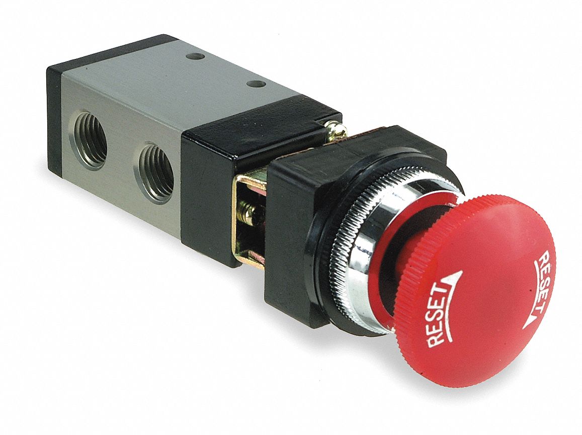
ARO, M Series, 3-Way/2-Position, Manual Air Control Valve - 3NA88

8+ pto air control valve diagram - VerityKenna

ARO 5/32" Manual Air Control Valve with 3-Way, 2-Position Air Valve

Idle Air Control Valve Wire Diagram Needed?

Flow Control Valve: Definition, Types, Components & Working Principle

Idle Air Control Valve Location: Where Is the Location of the Idle...
